Introduction
JBC is one of the most renowned soldering equipment manufacturers in the world. Most famously, JBC makes the C245 cartridge range, which feature an integrated design containing a thermocouple and heater wire. This construction method offers better performance and can be more compact than older, non thermally bonded tips.
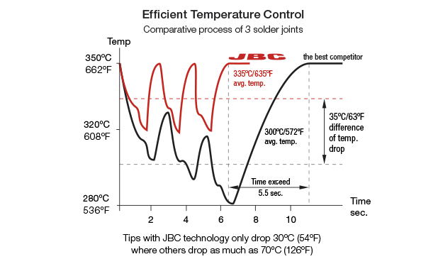
The only problem is that these stations are fairly high-end. The cheapest one I can find on their website is 500€ before VAT and shipping. A bit out of my budget, I think :(
On the other hand, the proprietary magic is contained in the cartridge construction. Those are disposable and hence cheap-ish (~30€).
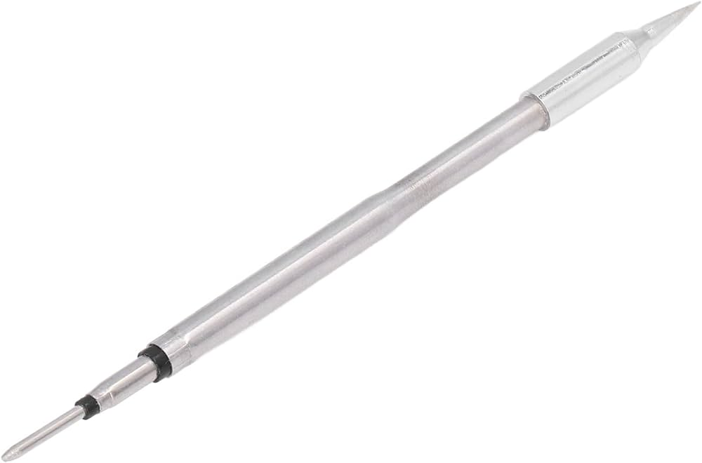
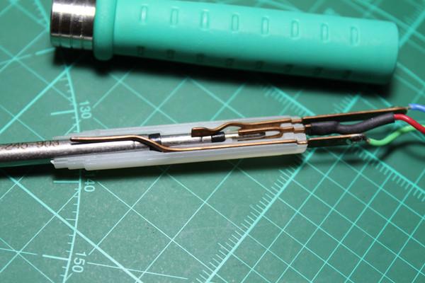
The tip plugs into a handle (T245) which only contains some contacts and a cable to the station.
State of the art
It doesn’t take a genius to realize that the driving circuit/station has a huge markup, so of course the internet is flooded with DIY solutions that can be built for a fraction of the price. Let’s take a loop at a non-exhaustive list:
Unisolder
Unisolder is a one-size-fits-all solution, meant as a “universal” soldering station.
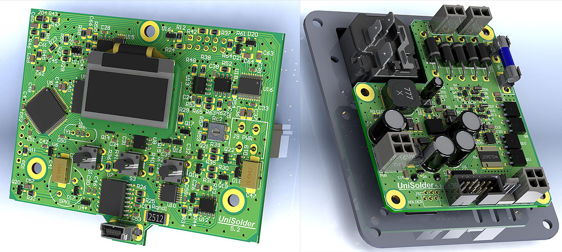
It’s hugely complex as it supports multiple types of sensors, heaters and includes two channels. As a consequence, the BOM cost is a bit scary.
Marco Reps’ JBC station
This was the topic of an old video from Marco Reps. It was constructed with a home-etched PCB.
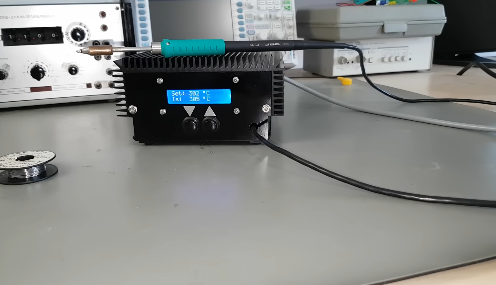
It’s quite cleverly built, with an isolated solid-state relay made of tiny MOSFETs. However, it requires a 2-output transformer (usually more expensive and bigger) and is made for the T470 handle instead of the T245 handle.
Otter Iron Pro
Otter Iron Pro is a USB-C PD powered station. It’s absurdly tiny, perhaps a bit too much for any practical use
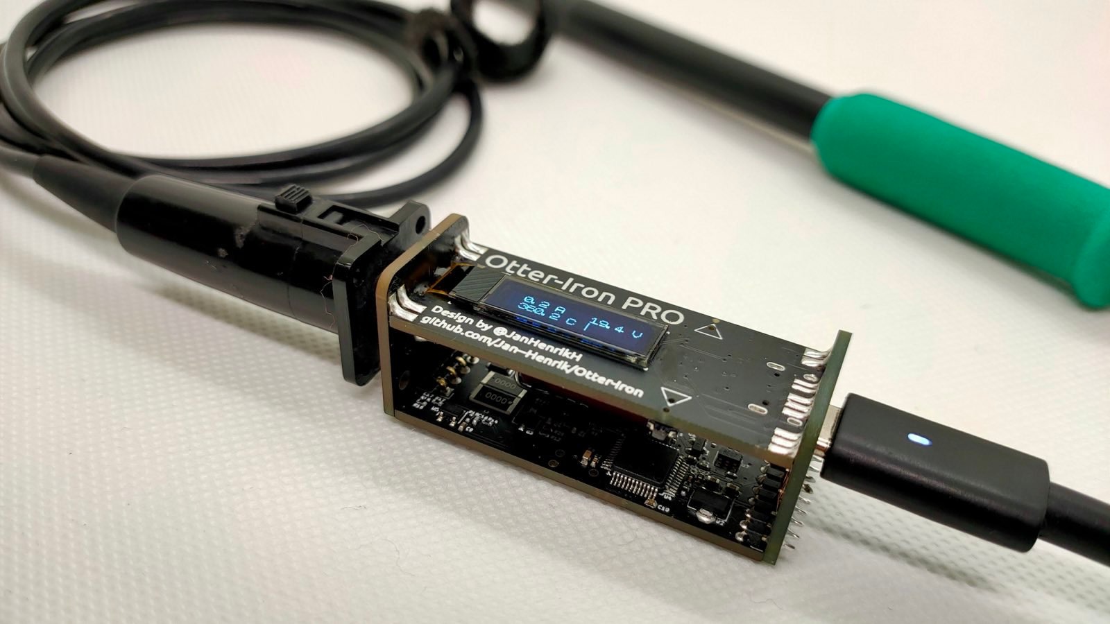
I mention it here because it uses DC power, unlike the first two projects. However, this driving scheme usually creates a lot of EMI so it should be avoided if possible.
Technical challenges
To decide what’s best for our design, let’s go over the technical basics.
The tip
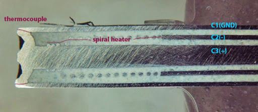
The tip (or cartridge, as JBC calls it) exposes three contacts. It is constructed with three coaxial tubes made of different materials and a coil of heating wire. Below is a cross-section of a C245 tip. The center tap (C3) will be called COMM, the outer casing (C1) will be called TC and C2 will be called HEAT.
Because of the thermoelectric effect, transitions between materials create various thermocouples throughout the circuit. Below is a crude sketch of what is happening inside the tip:
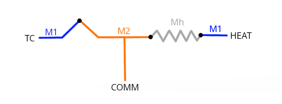
The “main” thermocouple is the one created between TC and COMM in the junction of materials M1-M2. One curious effect of this design is that if all the junctions are at the same temperature, M2-Mh-Mh-M1 create a thermocouple equivalent to M1-M2, only in reverse 1 . This means that the voltage between TC and HEAT is usually (and confusingly) zero.
For practical purposes, however, this effect can be ignored. The tip is thus represented as follows:
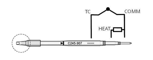
As for the technical details:
The heater has a resistance of about 2.5 Ω at room temperature (the resistivity of the material will increase as the temperature goes up)
The thermocouple is not a standard type K one. It seems to be a proprietary mix with a linear coefficient of around 23 µV/°C. As far as I know, nobody has characterized it for non-linearity (and it probably doesn’t matter much). This means that a gain of ~320 is needed for a 3.3 V ADC.
Grounding challenges
As you may have noticed, the TC contact is exposed to the exterior. This is intentional: the station is meant to connect this pin to protective earth directly, protecting the operator (and the station) in the event of a fault.
To visualize why this is a problem, let’s try a naive solution:
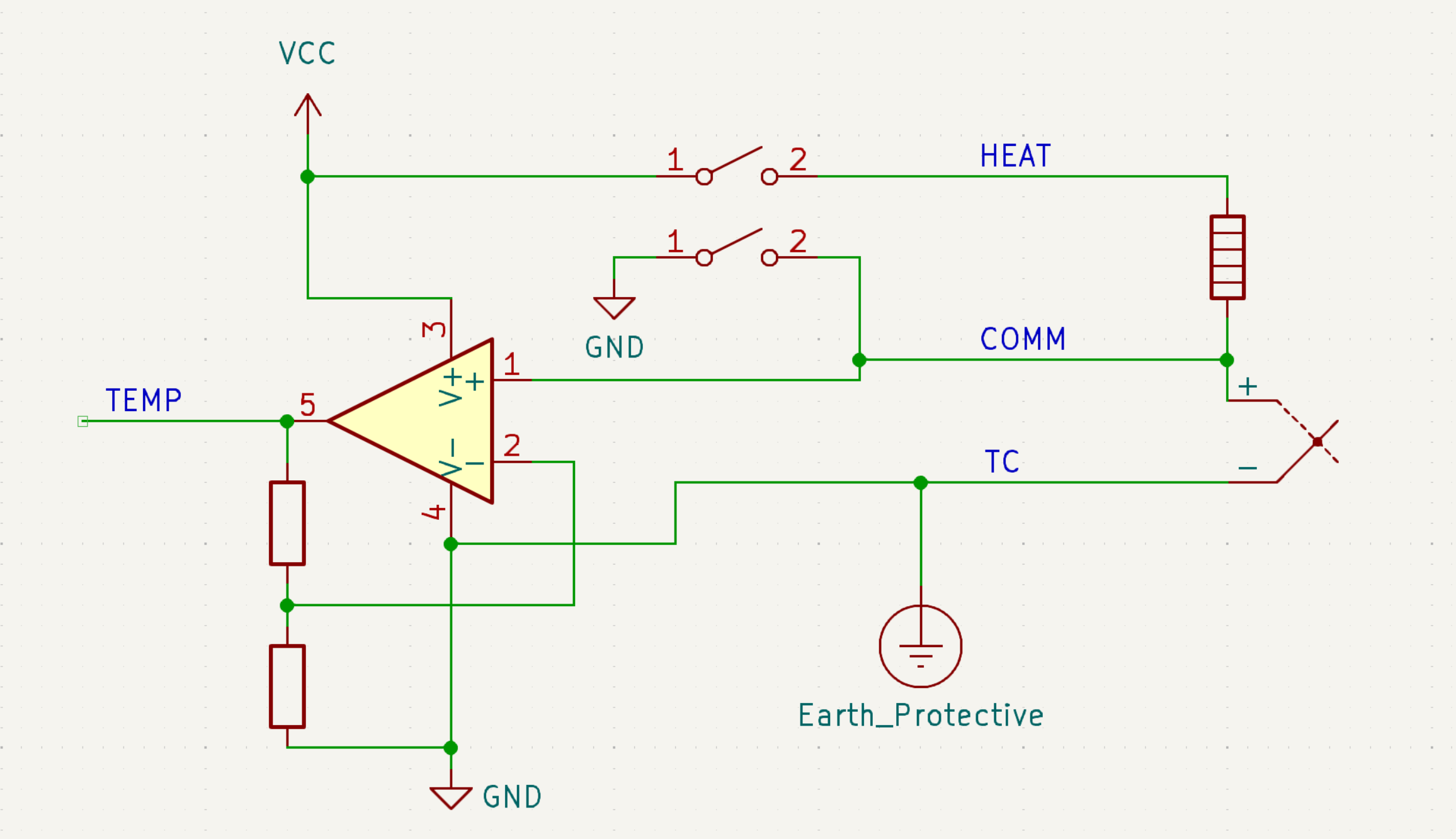
Because the TC terminal must be connected to PE, the power supply is referenced to PE. As Marco Reps explains, this creates an escape path for the disruptive heater current to exit through the thermocouple (and perhaps to protective earth).
Electromagnetic Interferece (EMI)
Although this line of cartridges is rated for around 50 W continuous power, there’s a reason that “real” JBC stations are rated for ~130 W. With a heater resistance of 2.5 Ω and 23.5 V as used in official station, these irons can take upwards of 200 W (peak). Connecting such a big instantaneous load on and off will create a lot of EMI.
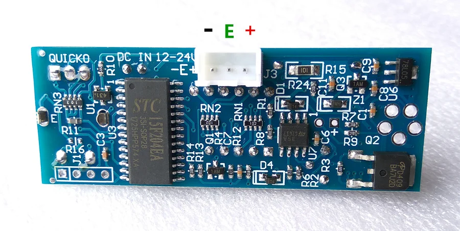
For this reason, “respectable” soldering stations use a clever trick: instead of a DC supply, AC power is used. By connecting and disconnecting the heater near or at the zero-crossing point, EMI and transformer humming can be minimized.

What options are there?
To summarize, the ideal controller board would have:
- A grounded tip
- An AC switching configuration
Additionally, it would be nice to achieve:
- Low BOM cost (and ideally use as few different components as possible)
- Good efficiency
- Compact implementation
After doing some research on existing implementations, I’ve noticed there are two different ways to approach this problem.
Option #1: isolated supply and solid state relay
To avoid the aforementioned grounding problems, this solution uses an isolated heater driving current, driven through an isolated Solid State Relay (SSR). The controller power supply is referenced to protective earth.
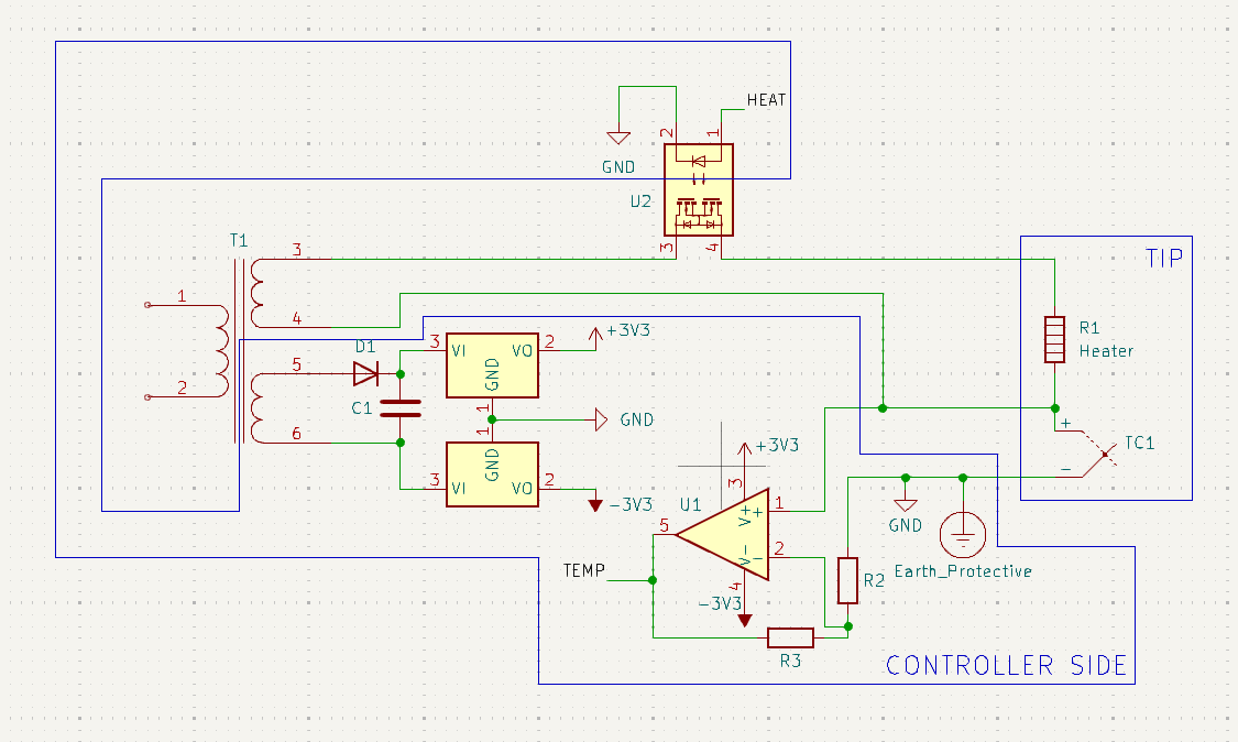
This solution was introduced to me by Marco Reps’ video on the topic, but I have since discovered through an EEVBlog forum post that official JBC stations use the same idea.
On paper, it has quite a lot of advantages:
Nearly unbeatable efficiency: with modern, low RDS(on) MOSFETs and zero-cross switching, nearly no power is lost to heat.
Potential for compact implementation: thanks to its incredible efficiency, no bulky power parts are required.
Only requires a single op amp: no instrumentation or differential amplifiers needed.
However, it should also be noted that:
Off-the-shelf transformers do not come in the necessary voltage and power ratings required for this design. This leaves us with two choices:
- Use a larger transformer with more rated power than necessary
- Wire a custom transformer: for mass production, these can be ordered for a reasonable price
Prototyping with AC current is less forgiving than with DC current.
Option #2: rectified AC switching with differential amplification
This solution uses a single floating power supply and a differential amplifier to read the thermocouple voltage. To simplify the driving circuitry, the incoming AC current is rectified before being used (and part of it buffered to power the controller):
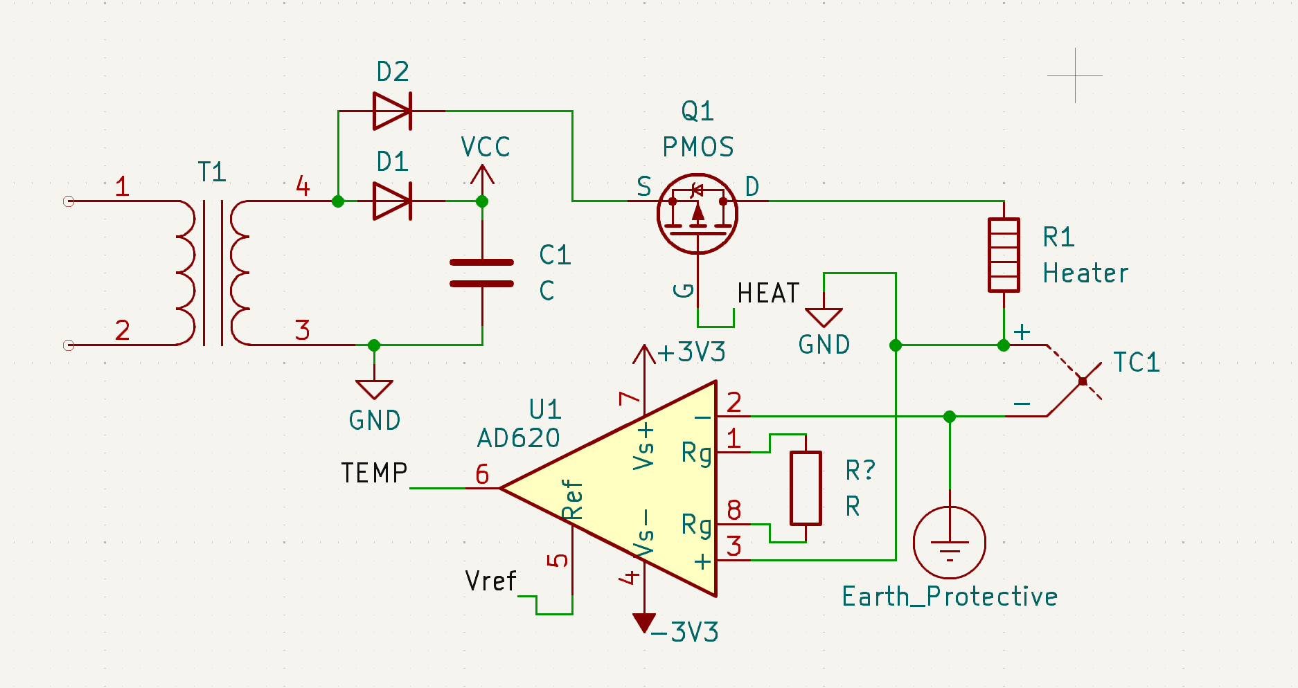
This solution is used by the Unisolder project and by the new PACE ADS200 station, a direct competitor to JBC.
The disadvantages are quite clear:
Inferior efficiency due to losses in rectification: this can be mitigated with an active rectifier.
An instrumentation amplifier 2 is more complex and expensive than a single low offset voltage op amp.
On the other hand, this design offers:
Greater flexibility on the type of power supply: it’s possible to power the station via a DC power supply and use PWM switching. This can be used to validate the design with a protected power source.
Smaller transformer options: because only one output is needed, the optimal transformer can easily be found on major electronics distributors.
More to come
Phew, that’s a lot of talking! In the next post I will attempt to assemble a prototype based on these ideas. Stay tuned!